
Topology
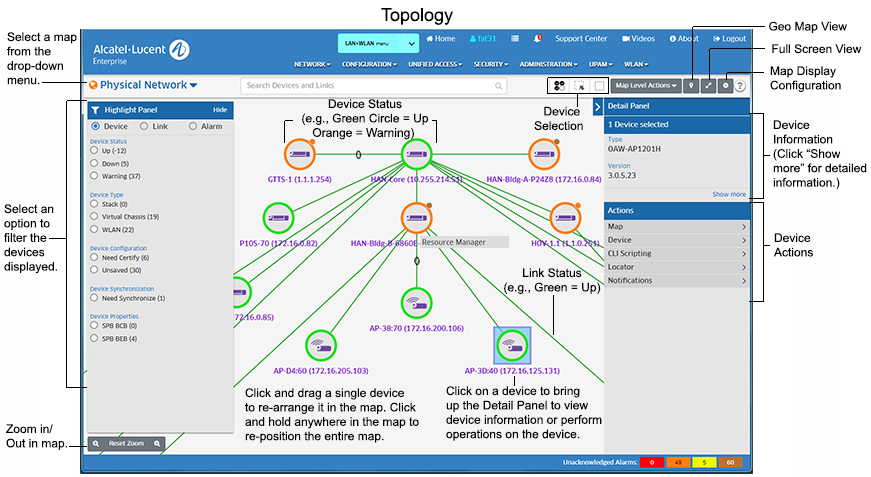
The Topology application enables you to view the topology of all managed devices in the network, view information about a specific device and perform certain actions on those devices (e.g., edit a device, telnet to a device, reboot a device). You can view devices in a topology map in various ways. For example, you can view managed devices in the Physical Network Map (default), and you can create custom maps that enable you to group and display devices in a way that is meaningful for your individual network configuration. You can also highlight specific devices or links, and re-arrange devices in a map and save that new map view. The figure below provides an overview of some of the functions that can be performed in the Topology application. Specific functions available when working with maps are detailed below.
Note: Devices must first be added to the Device Catalog and licensed before they are displayed in Topology. See the Device Catalog online help for more information. Also note that if your network contains APs, they are displayed in both the Physical Map and a Default AP Group Map that is automatically created when APs are added and licensed in the Device Catalog application.
Note: The default Topology Map view is the Geo Map view, which displays devices in their physical location on a geographical map. There are some device configuration options available in the Geo Map View; however most Topology device configuration options are available in the traditional Topology Map view shown below. When you first open OmniVista, the Geo Map view is displayed. Click on the Topology Map icon in the upper right corner of the Geo Map View to change to the traditional Topology view. You can also set the traditional Topology map view as the default view on the Topology Configurations Screen.
The Physical Network Map (shown above) automatically created by OmniVista and displays all managed network devices. The devices/maps you can see depend on your Role and permissions as configured in the Users and User Groups application (Security - Users and User Groups). You can also create Custom Maps, or configure Dynamic Logical Maps. These maps are logical maps created from devices in the Physical Network Map.
Note: You can click on the Map Level Actions drop-down at the top of the screen and select Go To Table View to view a list of all managed devices on the Managed Devices Screen.
Note: APs are displayed in both the Physical Map and a Default AP Group Map that is also automatically created by OmniVista. See the AP Registration Help for more information.
Note: If any devices in the displayed map have unsaved configuration changes in their Working Directory, a number will appear in the Notification icon (Bell icon) at the top of the screen. Click on the icon to see the number of devices in this condition. Click on the Save icon to save changes to the Working Directories of the devices.
Topology Maps
The Topology application not only provides an overview of the network, it can also be used to perform many functions that you can use to view and configure network devices. These functions are detailed in the following sections:
Working with Topology Maps
As mentioned earlier, the default Topology Map view is the Geo Map view, which displays devices in their physical location on a geographical map. There are some device configuration options available in the Geo Map View; however most Topology device configuration options are available in the traditional Topology Map view shown below. When you first open OmniVista, the Geo Map view is displayed. Click on the Topology Map icon in the upper right corner of the Geo Map View to change to the traditional Topology view. You can also set the traditional Topology map view as the default view on the Topology Configurations Screen.
This section details the traditional Topology Map view. In this view, you can highlight devices or links by different criteria (e.g., device type, device admin state, link admin state, alarm severity), change the map layout, search for specific devices in the map, or create maps. Note that the maps that you can view and the tasks you can perform in Topology (e.g., creating maps, creating devices) depend on your User Role and User Group (e.g., Administrator, Network Administrator) as defined in the Users and User Groups application).
Viewing Map Information
Topology maps provide a visual representation of the network. The administrative status of the device or link is indicated by color (described below), and detailed information can be displayed by clicking on device or link.
You can click on the Map drop-down in the upper-left corner to view different maps. The "Globe" icon in the drop-down displays the status of the highest-level notification of any device in the map (e.g., if all devices in a map are "Up", the icon is green, if a device in a map is a "Warning" state, the icon is orange, if a device in a map is "Down", the icon is Red). Note that when you click on the Map drop-down, you can click on the Pin icon to keep the drop-down open. Click the Pin icon again to close it.
Note: For a full screen view of Topology (without the OmniVista Cirrus Menu), click on the Full Screen icon in the top-right corner of the screen. Click the button again to return to the previous view.
Each device type is displayed with an icon as shown in the table below. You can also hover over a device or click on a device to view detailed device information. Device status (e.g., Up, Down) is displayed by the device status circle around the device. Notifications status is displayed in a small circle in the upper-right corner of the device. This indicates the status of device traps received (e.g., Normal, Minor). Note that this Notifications status is only displayed if traps have been configured on the device.
Device Icons |
||
OS2260/OS2360 |
OS6350 |
OS6360 |
OS6450 |
OS6560 |
OS6860/OS6860E/ |
OS6900
|
OAW AP |
|
Hover the mouse over a device to display basic information. Click on a device to open the Detail Panel and view detailed information about the device.
Device status is displayed by the device status circle around the device.
- Green = Device is "Up". For AOS devices, "Up" status does not necessarily mean that device is manageable from OmniVista. Refer to the "SNMP Status" column on the Managed Devices page for management status. For APs and other devices, "Up" indicates that the device is "Up" and manageable from OmniVista.
- Orange = Warning (indicates that traps have been received on the device. The highest-level of trap received by the device is displayed (Green, Orange, Red) in the Notifications Status).
- Red = Device is unreachable and cannot be managed by OmniVista. However, it may still be "Up" and functional in the network. Refer to the Device Status definition in the Managed Devices online help for more details.
Note: The colors above are the default Device Status colors. You can change the colors using the Network Status Screen in the Preferences application (Preferences - User Settings - Colors - Network Status).
Notifications status displayed in the small circle in the upper right corner of the device, indicating the highest-level of trap received by the device:
- No Circle = Alarm status is Normal.
- Orange = Alarm status is Warning.
- Purple = Alarm status is Minor.
- Yellow = Alarm status is Major.
- Red = Alarm status is Critical.
Note: The colors above are the default Notifications colors. You can change the colors using the Alarms Screen in the Preferences application (Preferences - User Settings - Colors - Alarms).
Note: If any device in a Child Map is in anything other than "Normal" status, a notifications status will be displayed on the Child Map icon. See Creating Maps for more information on Child Maps.
Links between devices are displayed as a single line, whether there is a single link or multiple links.
- Green - Link is up. If there are multiple links, Green indicates all of the links are up.
- Orange - There are multiple links and at least one of the links is down. For example, only some of the ports of a linkagg are down while others are up; or one end of a link is up and the other end is down.
- Red - Link is down. If there are multiple links, Red indicates all of the links are down.
- Blue - Link status is unknown..
Manual links are displayed as a dashed line if there is a single manual link or if there are multiple links and all of the links are manual. If there are multiple links and at least one is not a manual link, the link is displayed as a solid line. Aggregate links are displayed with an ellipse. Multi-Chassis links are displayed with a black border on the outer edge and an ellipse.
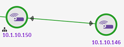
AP Mesh networks are displayed with Wi-Fi icons at endpoints between APs and a network symbol next to the Root AP in the network, as shown below.
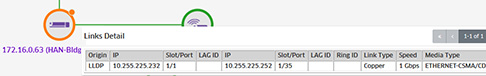
To display link information, move the mouse over the link until the pointer turns into a finger. Link information will be displayed in table form as shown below. The table displays information for all links.
You can also click on a link to display detailed link information. Move the mouse over the link until the pointer turns into a finger and click. The link is highlighted and link information is displayed in the Detail Panel. If it is a single link, the information is displayed for that link (as shown on the left below). If there are multiple links, a list of the links is displayed (as shown on the right). Click on a link to display details for the link. Click on the "Back" link to return to the list of links.
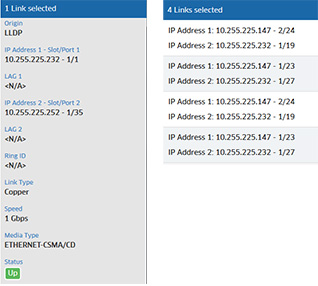
The information displayed varies depending on the link type.
- Origin - The origin of the link (LLDP, Manual).
- IP Address 1- The IP address of the first device in the link.
- Slot/Port 1 - The slot and port that connect the link on the first device, specified above.
- LAG 1 - If this is a link aggregation link, this field displays the Link Aggregation reference number assigned by the first device when the link aggregation group was created.
- IP Address 2 - The IP address of the second device in the link.
- Slot/Port 2 - The slot and port that connect the link on the second device, specified above.
- LAG 2 - If this is a link aggregation link, this field displays the Link Aggregation reference number assigned by the second device when the link aggregation group was created.
- Ring ID - The Ethernet Ring Protection (ERP) Ring ID, if applicable.
- Link Type - The link type (Copper or Fiber).
- Speed - The link speed.
- Media Type - The media type of the link.
- Status - The link status (Up, Down, Unknown).
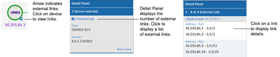
Note that when viewing a map, devices linked to a device in another map display an External Link arrow icon, as shown below. When you click on one of these devices, a link to display a list of external links appears at the top of the Detail Panel (e.g., "1 External Link", "4 External Links"). Click to display a list of external links, then click on a link in the list to display link details.
Note: The External Link detail display is not supported on Mesh AP Bridge External Links.
When you zoom out for an overview of the network, devices are grouped into clusters, as shown below. Devices are grouped based on their proximity to each other in the map. Each cluster displays the status of devices in the cluster and the number of devices in the cluster, along with a Trap Status indicator at the top of the cluster.
You can configure the minimum number of devices required to be displayed in a map to trigger the Clustering Feature. In other words, clustering will not be enabled unless there is this minimum number of devices in a map. The setting is found in the Topology Settings Screen.
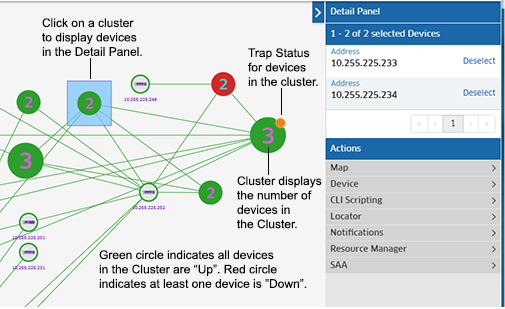
If all devices in a cluster are "Up", the cluster circle displays in Green. If any device in the cluster is "Down", the cluster circle displays in Red. Click on a cluster to display all of the devices in the cluster in the Detail Panel. You can then click on a device to view device details or perform an action on the device.
The small circle at the top of the cluster displays the status of the highest severity trap generated by any device in the cluster. For example, if the highest-level severity trap for any device in the cluster is "Warning", the circle will be Orange. If the highest-level severity trap for any device in the cluster is "Critical", the circle will be Red. If all traps generated by all devices in a cluster are "Normal", the Trap Status circle will not be displayed. The default trap status colors are shown below.
- No Circle = Alarm status is Normal.
- Orange = Alarm status is Warning.
- Purple = Alarm status is Minor.
- Yellow = Alarm status is Major.
- Red = Alarm status is Critical.
Note: You can change the default colors using the Alarms Screen in the Preferences application (Preferences - User Settings - Colors - Alarms).
Customizing Maps
You can customize the map display (e.g., Default Map, Map Color Scheme) and map layout.
You can change the default map preferences (e.g., Default View, map colors, link priority) by clicking on the Configuration icon at the top right corner of the map to bring up the Configuration Window (shown below). Set a preference(s) and click on the Save button. The changes will take effect immediately.
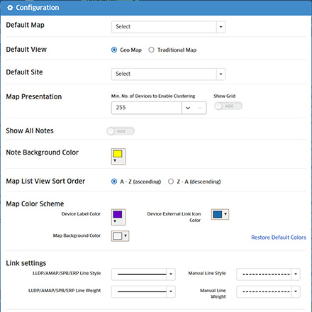
- Default Map - Used to set the default map displayed when you log into OmniVista Cirrus. Select a map from the drop-down menu to set the default map. By default, the Physical Network Map is displayed.
- Default View - Used to set the default map view. You can set the default view or the Geo Map view. No matter which view you are in when using the Topology application, you can toggle between the views.
- Default Site - Used to set the default Geo Map Site that is displayed.
- Map Presentation
- Min. No. of Devices to Enable Clustering - The minimum number of devices that must be displayed on a map to trigger the Clustering Feature. In other words, clustering will not be enabled unless there is this minimum number of devices in a map. "1" will enable clustering for every map.
- Show Grid - Show or Hide the Topology Map Grid. When you move devices on a map, they snap to gridlines in the map to enable you to be more precise in your placement of the device in the map. By default, the gridlines are not shown. move the slider to Show, to display the gridlines on the map. Note that showing the gridlines will impact performance. It is recommended that the gridlines be shown only for arranging devices.
- Show All Notes - Set whether or not to display Map Notes.
- List Map View Sort Order - Used to set the default list order for maps in the Map drop-down menu alphabetically in ascending (A-Z) or descending (Z-A) order. You can always temporarily change the list order by clicking on the sort order in the Map drop-down menu. The order will return to the default setting when you navigate away from the Topology application.
- Map Color Scheme - Click on the arrow next to a field to configure a different color, click Choose, then click on the Save button. The changes take effect immediately.
- Device Label Color - The color of the label under a device (e.g., IP address).
- Map Background Color - The color of the background for all maps.
- Device External Link Icon Color - The color of the device external link icon. If a device in a map has a link to a device that is not in the currently-displayed map, a small arrow is displayed in the lower right corner of the device.
- Link Settings - Used to set the Line Style and Line Weight you want to use when displaying LLDP/AMAP/SPB/ERP Links and Manual Links.
- Link Priority - Used to set the order in which links are displayed in the Details Panel when a multiple link is selected on a map.
- Ignore Manual Link - If enabled, manual links will be hidden when LLDP and manual links exist between a set of ports when hovering the mouse over the link; and the manual links will not be displayed in the Detail Panel after clicking on the link.
Note: You can change the information e.g., IP address, Device Name, DNS Name) displayed under device on a map using the Device Naming Screen in the Preferences application (Administrator - Preferences - User Settings - Device Naming). This changes the how devices are identified and displayed in all applications in OmniVista.
You can change the basic layout of a map by clicking on the Map Level Actions drop-down and selecting one of the following:
- Circular Layout - Arranges all of the devices in a circular pattern.
- Aligned Layout (Default) - Arranges all of the devices in rows.
- Circularize Connected Nodes - Select a device in the map and click on this option to display all nodes connected to the selected device in a circular pattern.
You can also change the layout of a map by selecting a device and dragging it to a new location. You can also select multiple devices and move them. (Note that there is a built in gridline in all maps to enable you to be more precise in your placement of a device, and devices will snap to this gridline when moved.) Click on the Save icon at the top of the map to save the layout changes. You can also zoom in or out on a map using the Zoom control at the bottom of the map; and you can move an entire map on the screen by clicking anywhere outside the map and dragging the map to a new location on the screen.
Note: If try to leave a map view or leave the Topology application without saving the new layout, you will be prompted to save it. Click Save at the confirmation prompt to save the new layout. The map will appear with the new layout the next time it is opened.
Adding Notes to Maps
You can add notes to any Topology map. Click on the Map Level Actions drop-down and select Add Note.
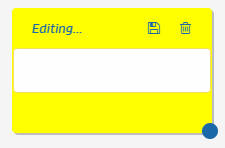
Enter any text for the note, then click on the Save icon. You can resize the window and move the Note anywhere on the map. Once a Note has been added, you can edit it by clicking on the Edit icon in the Note. Click on the Delete icon, then click on Delete This Note at the Confirmation Prompt. You can hide notes by toggling the Show All Notes field on the Topology Configuration Window.
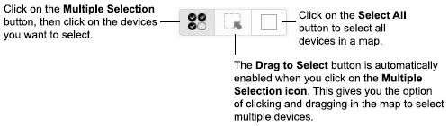
Selecting Devices
You can select a single device in a map to perform an action by clicking on the device. If you want to select multiple devices for an action, click on the Multiple Selection button at the top of the map, and click on the devices you want to select. When you click on the Multiple Selection button, the Drag to Select button is also enabled. At this point, you can either click on multiple devices to select them, or click and hold the mouse button to drag and select multiple devices. You can also select all devices in a map by clicking on the Select All button at the top of the map.
When you select multiple devices, the devices appear in a list in the Detail Panel on the right side of the screen (click on the Reselect button to remove a device from the list). You can then select an action (e.g., Copy Devices to Map, Poll for Traps, Reboot) to perform on the devices. Note that the actions available depend on the device type(s) selected and whether or not you select a single device or multiple devices.
Highlighting Devices/Links/Alarms
You can filter devices or links in a map by selecting one or more of Highlight criteria on the left side of the screen (Highlight Device, Highlight Link, Highlight Alarm). When you select one or more of the criteria (e.g., Status Up, Stack, Critical Alarm), only those devices/links matching the all of the selected criteria are displayed in the map. To return to the original map view, click on the "Clear" or "Clear All". You can filter devices/links based on the following criteria.
- Device
- Device Status
- Up
- Down
- Warning
- Device Type
- Stack
- Virtual Chassis
- WLAN
- Device Configuration
- Need Certify
- Unsaved
- Device Synchronization
- Need Synchronize
- Device Properties
- SPB BCB (Backbone Core Bridge)
- SPB BEB (Backbone Edge Bridge)
- Device Status
- Link
- Link Status
- Up
- Down
- Link Type
- Aggregate
- Manual Link
- Discovered Link
- Mesh Link
- Alarm
- Critical
- Major
- Minor
- Warning
- Normal
Searching for Devices/Links
You can search for a device(s) or link(s) in the currently displayed map or in all maps. Click on the "Search Devices and Links" area at the top of the screen to see a list of search criteria that you can search on (e.g., IP address, MAC address, Link Title, IP address 1). By default, the "Limit search to the current map" checkbox is enabled. If you want to search in all maps, de-select the checkbox.
Enter the search information. Any device(s)/link(s) matching the criteria will be displayed in a list below the Search area. Click on an item to highlight the device/link in the map. Click on the x in the "Search" area to delete the search criteria and begin a new search.
Creating/Cloning/Editing/Deleting Maps
The Physical Network Map view (Default) displays all network devices. You can also create Custom Maps, or configure Dynamic Logical Maps. These maps are logical maps created from devices in the Physical Network Map. You can create multiple maps (Custom and Dynamic), and a device can be included in multiple maps.
Note: Admin Users can create/clone/edit/delete maps. Netadmin and Write Users can edit maps.
By default, all discovered devices are initially displayed in the Physical Network Map that is automatically created by OmniVista. New maps can be created by configuring a Child Map from a Parent map, or by creating a Logical Map that is not associated with a Parent Map.
- Child Maps - Child Maps are sub-maps created from a Parent Map. Any device you add to a Child Map is moved from the Parent Map to the Child Map. In general, you would create a series of Child Maps from the Physical Map to organize your network view. Child Maps are displayed in the Map drop-down under their Parent Map, and displayed in the Parent Map as a Globe icon (see below). You can click on the Map icon to view the devices in the map.
- Logical Maps - Logical Maps are not associated with a Parent Map. They are just logical groupings of devices that you can create to better visualize and manage your network. Since you are not using a Parent Map to create the Logical Map, devices you add to a Logical Map are not removed from any other map, and are displayed in both maps.
![]()
To create a map, click on the Map Level Actions drop-down at the top of the screen and select New Map. The Create Custom Map window will appear. Complete the fields as described below to create a new map. When you are finished, click on the Create button to create the map.
- Map Name - Enter a unique name for the map. You cannot duplicate the name of an existing map.
- Background - If you want to change the default background for the map, select an image option, then select the background from the drop-down menu:
- Upload New - Click on the Browse button to locate a new background image, then select the image from the drop-down menu.
- Existing Images - Select an existing image from the drop-down menu.
- Dynamic Map (to create a Dynamic Map) - You can use a filter to create a Logical map that will dynamically add/remove devices to/from the map. Set the Dynamic Map slider to "On". Click on the Filter button to bring up the Filter Selection Window, and select a filter to apply to the map. If necessary, click on the Create icon to create a new filter. Select a condition(s) for the filter (e.g., IP address, Device Type, Device Location, AP Group.) Devices will now be added to/removed from the map dynamically based on the applied filter.
- Parent Map - If you want to create a Sub-Map of an existing map, select the Parent Map you want to use. Any devices you add to this map will be removed from the Parent Map and added to this map. If you want to create a Logical Map, select None. Selected devices will not be removed from the displayed map.
- Devices - Select the devices you want to include in the new map. Remember, if you are using a Parent Map to create a sub-map, the devices will be removed from the Parent Map and added to this new map. If you are creating a Logical Map (no Parent Map), the devices will be displayed in both maps.
Note: You can also copy devices from one map to another using the "Copy Device to Map" action. See Performing Device Actions for more information.
Note: If there are performance issues in rendering larger maps, you can reduce the number of devices in the map to improve performance.
You can also "clone" an existing map to quickly create a new Logical Map. Select a map that you want to clone from the Map drop-down menu at the top of the screen. Click on the Map Level Actions drop-down at the top of the screen and select Clone Map. The Clone Map window will appear with all of the devices in the map you are cloning pre-selected. Enter a Map Name and complete the fields as described above to create a new Logical Map.
Go to the Map drop-down and select the map you want to edit. When the map is displayed, click on the Map Level Actions drop-down at the top of the screen and select Edit Map. Edit any of the fields as described above and click on the Apply button. You cannot edit the map name. You cannot change a Logical Map to a Dynamic Map or a Dynamic Map to a Logical Map; however, you can edit the filter for a Dynamic Map. Note that you cannot edit an AP Group Map.
To delete a Map, go to the Map drop-down in the upper-left corner of the screen and select the map you want to delete. When the map is displayed, click on the Map Level Actions drop-down at the top of the screen and select Delete Map. Click OK at the Confirmation Prompt. If you delete a Logical Map, the map and all devices (and child maps, if applicable) will be deleted. If you are deleting a Child Map created from the Physical Map, the map will be deleted and all devices will be moved back to the Physical Map. Note that you cannot delete the Physical Network Map or any AP Group Maps.
The Map drop-down in the upper-left corner of the screen displays the name of the current map. To change to a different map, select the map from the drop-down menu. You can also search for a specific map in the list.
Working with Geo Maps
The Topology application provides a Geo Map view to display devices in their physical location on a geographical map. When a device is added to OmniVista Cirrus, you have the option of specifying a Geo Map location for the device (either street address or Latitude/Longitude). The device will then be displayed in the Geo Map view in Topology. You can also create Map Sites (e.g., Street/City, Data Center, Campus Building), place them in a specific Geo Location and add devices to those sites. The sections below detail the steps for adding a Geo Map location for a single device, working with Geo Map Sites, and viewing Geo Maps.
Adding a Geo Map Site Location for a Single Device
When you manually add a device to the Device Catalog, you have the option of specifying a Geo Map Site Location for the device. You do not have to specify a Geo Site Location when first adding a device, you can edit the device at any time on the Managed Devices Screen and specify a Geo Location. You can also include a Geo Site Location for devices when importing devices in bulk in a .csv file, or when adding devices using the OV Cirrus Assistant Mobile App. See the Device Catalog Help for detailed instructions on adding devices.
Geo Map Sites
You can create a Geo Map Site (e.g., Street/City, Data Center, Campus Building) and group devices in the site. When you create a Site, a logical map is automatically created for the Site. Note that you can create a Site without adding devices. Devices can be added/removed to/from a Site at any time. Also note that a device can only belong to one Site at time. To move a device to another Site, you must remove it from its current Site and add it to another Site. The sections below detail creating/editing/deleting Geo Map Sites.
You can also create Sub-Sites. For example, you might want to create a Campus Location, then add devices to a specific building and floor on the campus.
Creating a Geo Map Site
Click on the Create Site button in the Topology Geo Map view or on the Device Catalog Screen. You can also click on the Map Level Actions drop-down in the traditional Topology view and select New Site. The Create Site Window will appear.
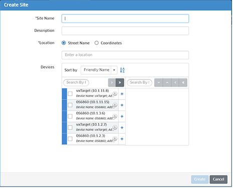
Complete the fields below and click on the Create button to create a new Site.
- Site Name - User-configured name for the Site.
- Location
- Street Name - Enter a location beginning with the street name, city, etc. (OmniVista will offer suggestions as you type).
- Coordinates - Enter Latitude and Longitude of the Site.
- Description - Optional description for the Site.
- Devices -Any devices that have not yet been assigned to a Site will be displayed on the left. Move the devices to the right to add them to the Site. Note that you can create a site without adding devices. Devices can be added later to the Site, or you can create Sub-Sites (e.g., building, floor) and add devices to the Sub-Sites. Also note that a device can only belong to one Site or Sub-Site. To move a device to another Site or Sub-Site, you must remove it before adding it to another Site or Sub-Site. If you remove a device that has a Geo Location specified and do not add it to another Site or Sub-Site, the device will be displayed individually on the Geo Map.
Note: Remember that a device can only belong to one Site or Sub-Site at a time. If you are planning on creating Sub-Sites within a Site, it is recommended that you create a Site without assigned devices, then assign devices when you create the Sub-Sites (e.g., Floor 1, Floor 2).
Creating Sub-Sites
You create Sub-Sites within a Site (e.g., buildings, floors) by creating child maps from the logical Site map that is automatically created when you create a Site. To create a Sub-Site, go the Site map in the traditional Topology view. Click on the Map Level Actions drop-down at the top of the screen and select New Map. The Create Custom Map window will appear. The name of the current Site map will be displayed in the Parent Map field. Enter a Sub-Site Map Name (e.g., Building 1, Floor 1), add devices to the map, and click on the Create button. Remember that just as in Sites, a device can only be assigned to one Sub-Site at a time.
The new Sub-Site map will appear as a sub-map under the Site in the Map drop-down at the upper-left corner of the screen. When you go to the Geo Map view, the total number of devices at the Site will be displayed in the Site circle (the total number of devices at the Site including all Sub-Sites), along with the device status and notifications status for all devices at the Site.
If all devices in a Site are "Up", the Site circle will be Green. If any device at the Site is in a "Warning" state, the Site circle will be Orange. If any device at the Site is "Down", the Site circle will be Red.
The small, solid circle in the upper-right corner of the Site circle displays the status of the highest severity trap generated by any device at the Site. For example, if the highest-level severity trap for any device at the Site is "Warning", the circle will be Orange. If the highest-level severity trap for any device at the Site is "Critical", the circle will be Red. If all traps generated by all devices at the Site are "Normal", the Trap Status circle will not be displayed. The default trap status colors are shown below.
- No Circle = Alarm status is Normal.
- Orange = Alarm status is Warning.
- Purple = Alarm status is Minor.
- Yellow = Alarm status is Major.
- Red = Alarm status is Critical.
Editing a Geo Map Site
You can edit a Geo Map Site by right-clicking on the site and selecting Edit Site. The Edit Site Window will appear. You can edit the Site Description or Location, and add/remove devices to/from the Site. If you remove a device, it will then be available for another Site. If you remove a device that has a Geo Location specified and do not add it to another Site, the device will be displayed individually on the Geo Map.
You can also go to the Logical Map for the Geo Map Site to edit the Site. If you are in the traditional Topology view, select the Site from the Map List drop-down in the upper left corner of the screen. If you are in Geo Map view, hover the mouse over the Site on the Geo Map and click on Go to Topology to open the Logical Map for the Site. On the Logical Map, click on the Map Level Actions button at the top of the screen and select Edit Site.
Note: Just as in the traditional Topology view, if you right-click on an individual device in a Geo Map, the Actions drop-down menu will appear, enabling you to perform any available device actions.
Deleting a Geo Map Site
You can delete a Geo Map Site by right-clicking on the site and selecting Delete Site. Click on Delete at the Confirmation Prompt. All devices will be removed from the site. If a device had a Geo Location specified, once you remove it from the Site, it will be displayed individually on the Geo Map.
You can also go to the Logical Map for the Geo Map Site to delete the Site. If you are in the traditional Topology view, select the Site from the Map List drop-down in the upper left corner. If you are in Geo Map view, hover the mouse over the Site on the Geo Map and click on Go to Topology to open the Logical Map for the Site. On the Logical Map, click on the Map Level Actions button at the top of the screen and select Delete Site. Click on Delete at the Confirmation Prompt.
Note: Just as in the traditional Topology view, if you right-click on an individual device in a Geo Map, the Actions drop-down menu will appear, enabling you to perform any available device actions.
Viewing Geo Maps
If you are in the traditional Topology view, click on the Geo Location View icon at the top-right corner of the screen to display the Geo Map view. Like any map application, you can zoom in/out and drag the map to change the view. Map Sites and individual devices are displayed as shown below. For individual devices, the device status is displayed by color (e.g., Green, Red), as is the Notifications status. For Geo Map Sites, the number of devices, device status, and Notifications Status are displayed for all devices in the Site. Links between Sites and devices are displayed, if configured. The links status is either "Up" (Green) or "Down" (Red).
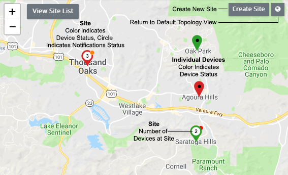
For individual devices, the device status is displayed by color (Green, Orange, Red). For Sites, if all devices at a Site are "Up", the Site circle displays in Green. If any device at the Site is "Down", the Site circle displays in Red.
The small circle at the top of the device icon or the Site icon displays the Notifications Status. For an individual device, it displays the highest severity trap generated by the device. For a Site, the Notifications Status displays the status of the highest severity trap generated by any device in the Site. For example, if the highest-level severity trap for any device at the Site is "Warning", the circle will be Orange. If the highest-level severity trap for any device at the Site is "Critical", the circle will be Red. If all traps generated by all devices at the Site are "Normal", the Notifications Status circle will not be displayed. The default Notifications status colors (for both sites and are shown below.
- No Circle = Alarm status is Normal.
- Orange = Alarm status is Warning.
- Purple = Alarm status is Minor.
- Yellow = Alarm status is Major.
- Red = Alarm status is Critical.
Note: You can change the default colors for alarm status using the Alarms Screen in the Preferences application (Preferences - User Settings - Colors - Alarms).
Note: You can change the default colors for device status using the Network Status Screen in the Preferences application (Preferences - User Settings - Colors - Network Status).
Click on the + or - symbol to zoom out or in on the map. Note that as you zoom out, Sites and devices that are close to each other on the map will display as a cluster with the number of Sites/devices displayed. When you zoom in, the individual Sites/devices will again be displayed.
Click on the View Site List button to view a list of Sites. You can then click on a Site in the list to center the map on the site. Click on the Create Site button to create a new Site (you can also click on the + icon at the top of the Site List to create a new Site). Click on the Topology View icon next to the Create Site button to return to the traditional Topology Map view.
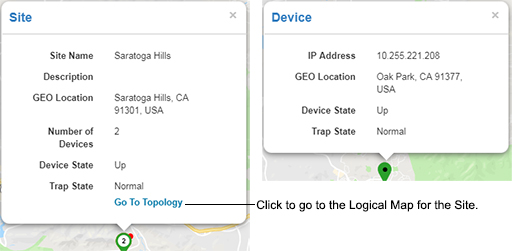
You can hover the mouse over a Site or an individual device for more detailed information. When you hover over a Site, a "Go To Topology" link is also displayed. Click on the link to go the Logical Map for the Site. Sites can only be edited/deleted from the Logical Map.
Working with Network Devices
You can view detailed information about a device or perform certain actions on a device by clicking on the device in the map. Actions can be performed on a single device or multiple devices. See Selecting Devices for instructions on selecting single or multiple devices. After selecting a device(s), you can perform one of the actions displayed in the Actions area. Note that the actions available depend on the device type(s) selected and whether or not you select a single device or multiple devices.
Note: The actions you can perform in Topology (e.g., performing backups, creating inventory reports) depend on your User Role and User Group configured in the Users and User Groups application.
Viewing Device Information
Click on a device to display detailed device information (IP address, MAC address, Backup information) in the Detail Panel on the right side of the screen. If you select multiple devices, the devices will be displayed in a list in the Detail Panel. Click on a device in the list to view information. Click on the “Back” link to return to the list. The information displayed may vary depending on the device.
- Type - The device type/model (e.g., OS6450-U24S)
- Version - The software version installed on the device (e.g., 6.7.2.107.R03).
- Address - The IP address of the device.
- MAC Address - The MAC address of the device.
- Serial Number - The serial number of the device.
- Status - The administrative status of the device:
- Up - Device is up and responding to polls.
- Warning - Device has sent at least one warning or critical trap and is thus in the warning state.
- Down - Device is down and not responding to polls.
- Location - The physical location of the device.
- System Contact - Contact information for the person responsible for the device.
- Name - The device name.
- DNS Name - The device DNS name, if applicable.
- Last Upgrade Status - The status of the last firmware upgrade on the switch:
- Successful - Successful BMF and Image upgrade performed.
- Successful (BMF) - Successful BMF upgrade performed.
- Successful (Image) - Successful Image upgrade is performed.
- Failed (BMF, Image) - BMF and Image upgrade failed.
- Failed (BMF) - BMF upgrade failed.
- Failed (Image) - Image upgrade failed.
- Backup Date - The date that the device's configuration and/or image files were last backed-up to the OmniVista Server.
- Backup Version - The firmware version of the configuration and/or image files that were last backed-up to the OmniVista Server.
- Last Known Up At - The date and time when the last successful poll was initiated on the device.
- Description - A description of the device, usually the vendor name and model.
- Traps - The status of trap configuration for the device
- On - Traps are enabled.
- Off - Traps are disabled.
- Not Configurable - Traps for this device are not configurable from OmniVista. (Note that traps may have been configured for such devices outside of OmniVista.) Unknown - OmniVista does not know the status of trap configuration on this device. OmniVista will read the switch's trap configuration when traps are configured for the switch via the Configure Traps Wizard.
- No. of Licenses Used- The total number of licenses being used. Generally, this will be 1. However, a device may use more than 1 license. For example, a stack of 4 switches would require 4 licenses, a VC of 6 would require 6 licenses. If a stack splits, the number of licenses reserved for the device before the split is maintained even though modules have been reduced to less than 5. This way, the license counts are reserved for the stack to recover.
- License Type - The type of license used by the device (e.g., Alcatel-Lucent Enterprise).
- Running From - For AOS devices, this field indicates whether the switch is running from the certified directory or the working directory. This field is blank for all other devices. For AOS devices, the directory structure that stores the switch's image and configuration files in flash memory is divided into two parts:
- Certified Directory - Contains files that have been certified by an authorized user as the default configuration files for the switch. When the switch reboots, it will automatically load its configuration files from the certified directory if the switch detects a difference between the certified directory and the working directory.
- Working Directory - Contains files that may or may not have been altered from those in the certified directory. The working directory is a holding place for new files to be tested before committing the files to the certified directory. You can save configuration changes to the working directory. You cannot save configuration changes directly to the certified directory.
Note that the files in the certified directory and in the working directory may be different from the running configuration of the switch, which is contained in RAM. The running configuration is the current operating parameters of the switch, which are originally loaded from the certified or working directory but may have been modified through CLI commands, WebView commands, or OmniVista. Modifications made to the running configuration must be saved to the working directory (or lost). The working directory can then be copied to the certified directory if and when desired.
Note: OmniVista supports the Multiple Working Directories Feature available on OS6900 Switches (AOS Release 7.2.1.R01 and later). This feature allows the user to create multiple Working Directories on the switch that can be used to save specific switch configurations. The user can create any name for these "Working" Directories (e.g., "Marketing Switch 05-10-19"). If the switch is running from one of these user-created directories, the directory name is displayed in this field.
- Changes - This field indicates the state of changes made to the switch's configuration. This field is blank for all other devices. This field can display the following values:
- Certified - Changes have been saved to the working directory, and but the working directory has been copied to the certified directory. The working directory and the certified directory are thus identical.
- Uncertified - Changes have been saved to the working directory, but the working directory has not been copied to the certified directory. The working directory and the certified directory are thus different.
- Unsaved - Changes have been made to the running configuration of the device that have not been saved to the working directory.
- Blank - When this field is blank, the implication is that OmniVista knows of no unsaved configuration changes and assumes that the working and certified directories in flash memory are identical.
- Synchronized Status - Indicates whether the primary CMM module's working directory is identical to the working directory on the other CMM module (if present):
- Synchronized - The primary CMM module's working directory is identical to the working directory on the other CMM module.
- Not Synchronized - The primary CMM module's working directory is not identical to the working directory on the other CMM module.
- Not Applicable - Only one CMM module is installed.
- Unknown - The synchronization state is unknown.
Performing Device Actions
You can perform the following actions on any device in a map. To execute one of the actions, click on a device(s) and select an action from the Actions area in Detail Panel. Note that the actions available are different for single device selection and multiple device selection. Available actions will also vary if you select different types of devices in multiple selection mode. Note that you can also perform actions on a device(s) by selecting a device(s) and right-clicking to bring up a menu of device actions. Click on a category, then click on an action. Note that you must right-click while the cursor is on a device to bring up the menu.
Map
- Overlay View - Provides detailed information for wireless, virtual chassis, and stack devices. Topology maps display
a single icon for Virtual Chassis, Stacks, and Wireless devices.
For example, topology maps display only the Master Chassis in a virtual chassis. You can select the device in the map and click on "Overlay View" to display the other the virtual chassis or stack. When the overlay view is displayed, you can click on any device in the overlay view for detailed information on the device. The following information is displayed:
- Virtual Chassis Overlay - Displays the devices in the Virtual Chassis and links between them. Click a node/link to view chassis/VFL link detail information.
- Stack Overlay - Displays each slot (chassis), and the links between them. Click on a node/link to view slot/link detail information.
- AP/Node Relationship Overlay - Displays information about APs and LAN Devices, as well as the link between them.
Click on an AP, switch or link for detailed information.
- AOS Switch - IP Address, MAC Address, Serial Number, Type, Status, SW Version, Location, System Contact, Name, DNS Name, Last Upgrade Status, Backup Date, Backup Version, Last Known Up At, Description, Traps, No. of Licenses Used, License Type, Running From, Changes, Synchronized Status.
- AP Nodes - IP Address, MAC Address, Serial Number, AP Type, Status, SW Version, Location, System Contact, Name, DNS Name, Last Upgrade Status, Backup Date, Backup Version, Last Known Up At, Description, Traps, No. of Licenses Used, License Type, Running From, Changes, Synchronized Status, AP Group, SSIDs, Management VLAN, Data VLANs.
- Link - Origin, IP Address 1, Slot/Port 1, LAG 1, IP Address 2, Slot/Port 2, LAG 2, Ring Id, Media Type, Status, Local Port VLANs, Remote Port VLANs.
- Copy Device to Map - Copies the selected device(s) from the current map to a different map. Select a device(s), click on the "Copy Device to Map" action link, then select the new map location from the Map drop-down at the top-left of the screen. When the new map appears, click on the Add devices to this map button. The device(s) will appear in the new map.
Device
- Edit Device - Opens the Edit Discovery Manager Screen in the Inventory application for the selected device.
- Delete Device - Deletes the selected device(s) from the map display. This is generally only used on Logical Maps. If you delete a device from the Physical Network Map or Default AP Group Map, you will have to restart the activation process on the device to have the device display in the map again. When you delete a device from a map, it remains in the Device Catalog.
- Device Inventory - Takes you the Inventory application's Managed Devices Screen.
- Ping Device - Causes an immediate ping of the selected device(s), and launches the Managed Devices Screen in the Inventory application to display the results.
- Poll Device - Causes an immediate poll of the selected device(s), and launches the Managed Devices Screen in the Inventory application to display the results.
- Poll Link - Causes an immediate poll of any links on the device(s), and launches the Managed Devices Screen in the Inventory application to display the results.
- View Ports - Takes you to the Inventory application's Ports Screen where you can view information for all ports on the device, and enable/disable ports.
- Copy Working/Running to Certified - Copies the contents of the working/running directory in the primary CMM to the certified directory in the primary CMM. Note that the Copy Working to Certified command also automatically synchronizes the switch's CMMs after the copy action is completed.
- Copy Certified to Working/Running - Copies the contents of the certified directory in the primary CMM to the working/running directory in the primary CMM.
- Save to Running - Saves the primary CMM's current running configuration to the current running directory of the switch. OmniVista supports the Multiple Working Directories Feature on certain devices (OS6900). This feature allows the user to create multiple "working" directories on the switch that can be used to save specific switch configurations. When the Save to Running Command is executed, the device(s) save the CMM's current running directory to the current user-defined "working" directory (Running Directory). Note that if you select a group of devices and some do not support multiple working directories, the devices will save the CMM's current running directory to the device's current "working" directory, whether it is a user-defined directory or the Working Directory.
- Configure Health Thresholds - Opens the Configure Device Health Thresholds Screen in the Inventory application for the selected device. Thresholds are used to set limits for health traps. If a device has been configured to send health traps, a trap will be sent whenever a monitored item's current utilization exceeds the configured health threshold. Configure the CPU, Memory, or Temperature Threshold for the selected device(s) and click on the Apply button. Note that you cannot configure the Temperature Threshold. The Temperature Threshold is hard coded on devices.
- Reboot - Takes you the Inventory application's Managed Devices Screen where you can reboot the selected device(s). On LAN Devices, you have the option of rebooting from the Working, Certified, or Other Directory and setting a time for the reboot. Use the Reboot From drop-down to select the directory you want to reboot from. In the Reboot Delay drop-down, select when you want to reboot to occur (now, a specific number of minutes from now, or at a specific date and time). Note that when you reboot multiple devices, there is a minimum delay of 30 seconds before the devices reboot (even if you select the Reboot now option).
CLI Scripting
- SSH/Telnet - Opens up an SSH or Telnet session with the selected device on the Terminal Screen in the CLI Scripting application.
Locator
- Locate End Stations - Launches the Locator application and searches for all end stations/clients (Stellar APs) that are attached to the selected switch. All end stations/clients found are displayed in the Locator application's Browse Screen.
Notifications
- View Traps - Launches the Notifications Home Screen in the Notifications Application to display traps for the selected device.
- Poll for Traps - Causes an immediate poll of the selected devices for traps. Traps are reported in the Notifications application.
- Configure Traps - Launches the Trap Configuration Wizard in the Notifications application to enable you to configure traps for the selected devices.
Configuration Manager
- Backup Device - Launches the Backup Wizard in the Configuration Manager application, which enables you to perform a configuration backup of the selected devices.